TM 3-6665-316-12
4-15.
R E P L A C E M E N T
8.
9.
10.
11.
12.
OF RECEIVER IN M43A1 DETECTOR (continued)
Push pins on M43A1 Interface Cable plug into holes on Test Connector
J10 until pins are fully seated.
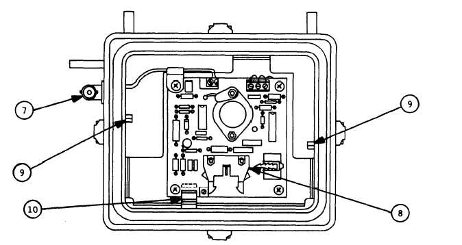
Position receiver on flat surface so receiver ring is up, extender is
down,
and
coaxial
connector
(7),
is
to
your
left.
Looking down into receiver ring, locate Connector P1 (8) on decoder
printed wiring assembly.
Position case-top assembly above receiver ring so word CAUTION and
black radiation hazard symbol are toward you.
C A U T I ON
The M43A1 Interface Cable must not interfere
with electrical spring contacts or Interface
Cable Retainer on inside of ring or extend
between case-top assembly and receiver ring
top surface or damage may result.
While guiding M43A1 Interface Cable out thru bottom of receiver
ring, lower detector internal components into receiver ring.
Be sure
none of M43A1 Interface Cable extends between case-top assembly and
receiver ring top surface.
Be sure cable does not interfere with
electrical spring contacts (9) or Interface Cable Retainer (10) on
inside of receiver ring.
4 - 30


