TM 3-6665-316-12
ASSEMBLY AND PREPARATION FOR USE (continued)
2-5.
Installation
of
Receiver
in
M43A1
Detector
d.
To
install
a
receiver
in
an
M43A1
Detector,
perform
the
following:
Position detector
so
that
the
words
24
VDC
INPUT
and
AIR
FILTER
are
1.
toward you.
2.
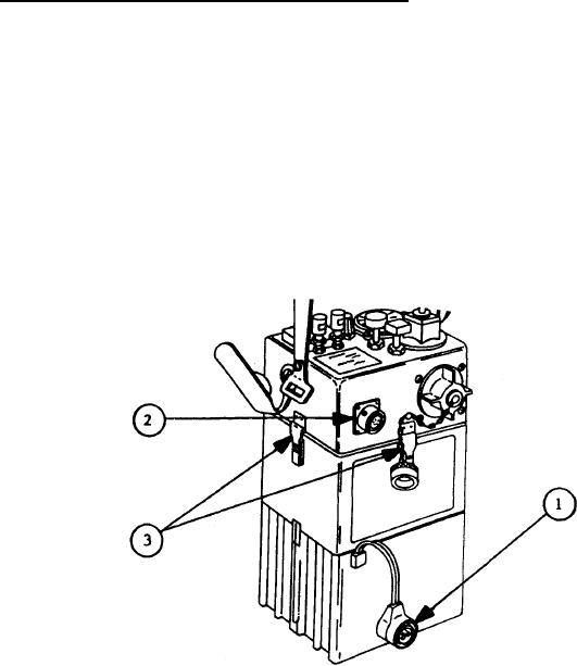
If detector is powered by BA3517/U Battery, pull out on BA3517/U
Battery Power Cable connector (1) until it is disengaged from 24 VDC
If detector is connected to any other power
INPUT connector (2).
source, turn power source connector lockring 1/4 turn counterclock-
wise, and then pull it away from 24 VDC INPUT connector until
connectors are disengaged.
Release four latches (3) holding detector case-top assembly to case-
3.
Disengage latches from catches on case-top
bottom assembly.
assemblv.
Pull up
on detector carrying handle until detector
internal
com-
4.
ponents
clear rim of case-bottom assembly.
5.
Position case-top assembly so word CAUTION and black radiation hazard
symbol on one face of case-top assembly are up, internal components
point up at an angle to your right, and case-top assembly rests on
carrying handle and one top edge (as shown).
6.
Remove
M43A1
Interface
Cable
from
transit
case.
7.
Line up pins on plug on
M43AI Interface
Cable with holes on 14-pin
Be sure keying
pins on two connectors line
Test Connector J1O (4).
up male-to-female.
Push
pins
on
M43A1
Interface
Cable
plug
into
holes
on
Test
Connector
8.
J1O
until
pins
are
fully
seated.
2-10

