
2-222
TM 3-4230-209-30&P
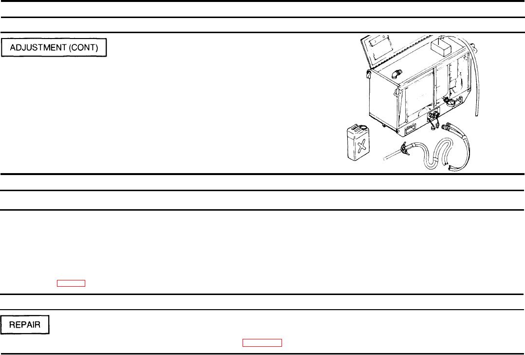
2-48. FUEL PUMP ASSEMBLY (CONT).
ACTION
REMARKS
LOCATION/lTEM
Power Cable to Pump Unit/
Step 15. Loosen the tube coupling nut at the adapter to allow fuel to
drain from the fabricated test line.
Step 16. Disconnect the fuel hose assembly from the water heater and
from the five gallon gasoline can. Dispose of fuel in accordance
with local directives.
Step 17, Roll up fuel hose assembly and power cable assembly, and
stow in the top cabinet storage area.
Step 18. Unscrew test line tube coupling nut from the rotary power-
driven pump. Reconnect the nozzle pressure line and retighten
the tube coupling nut.
Step 19. Restore the water heater to normal condition.
2-49. FUEL SUPPLY LINE.
This task covers repair.
INITITAL SETUP
Equipment Condition
Tools and Special Tools
Fuel supply line removed from skid base assembly.
Automotive Maintenance and Repair Field Maintenance
Shop Equipment, Basic, Less Power (SC 4910-95-CL-A31)
Materials/Parts
Fuel supply line (fig D-58)
ACTION
REMARKS
LOCATION/lTEM
Fabricate new fuel supply line according to figure D-58
Fuel Supply Line/