
2-136
TM 3-4230-209-30&P
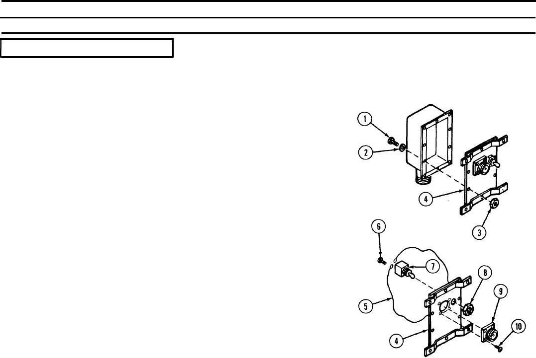
2-28. CONTROL PANEL ASSEMBLY (CONT).
LOCATION/lTEM
ACTION
REMARKS
DISASSEMBLY/REPAIR/REASSEMBLY
Alternator Junction Box/
Machine screws (1)
Remove six machine screws (1), lock washers (2), nuts (3), and cover (4).
All of the following listed items are supplied as part of
Lock washers (2)
the alternator junction box.
Nuts (3)
Cover (4)
Tag wires (5) to identify for installation on new switch. Unscrew and
Wires (5)
Screws (6)
remove two screws (6) securing wires (5) to toggle switch (7). Holding
Toggle switch (7)
toggle switch (7), unscrew and remove nut (8). Remove toggle switch (7).
Nut (8)
Tag and unsolder leads to electrical connector (9). Remove four machine
Electrical connector (9)
screws (10) and electrical connector (9).
Machine screws (10)
Replace ail unserviceable authorized parts.
Install electrical connector (9) and fasten with four machine screws (10).
Connect electrical leads.
Insert toggle switch (7) through switch hole in the case, screw nut (8) onto
toggle switch (7) threaded stem, and tighten.
Determine identification of wires from the tags applied earlier. Reconnect
wires (5) to correct toggle switch terminals with screws (6) and tighten.
Install cover (4), and secure with six lock washers (2), machine screws (1),
and nuts (3). Tighten.