
TM 3-4230-209-30&P
2-132
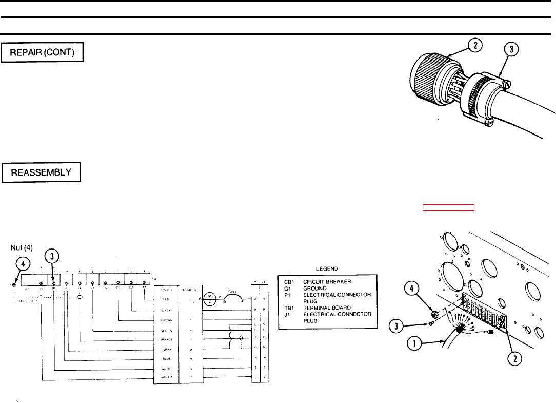
2-28. CONTROL PANEL ASSEMBLY (CONT).
REMARKS
ACTION
LOCATION/lTEM
Unscrew shell (3) of electrical plug connec-
Control Panel Assembly/
tor (2) and slide back on wires to gain access to
Electrical plug
unsoldered wires. Solder broken wire(s) or
connector (2)
replace electrical plug connector (2) as applicable.
Power Cable Assembly/
Solder connections will be soldered in accordance
Shell (3)
with MI L-S-6872.
Using an ohmmeter, check cable for continuity and shorts.
Control Panel Assembly/
NOTE
Using the wiring diagram, place the terminals of the color coded or tabbed
Power cable assembly (1)
Refer to paragraph 2-28 for wiring of
wires of power cable assembly (1) onto the correct terminals (B2, C3. E5,
TB1 (2)
pump unit including control panel
F6, H7, 16 and J9) of TB1 (2). Attach with seven screws (3) and tighten.
Screw (3)
assembly.
Reconnect shielded wire to G1, attach nut (4), and tighten. If not already
connected, connect power cable assembly (1) (see following diagram).