2-40
TM 3-4230-209-30&P
2-14. PUMP UNIT ASSEMBLY (CONT).
LOCATION/lTEM
ACTION
REMARKS
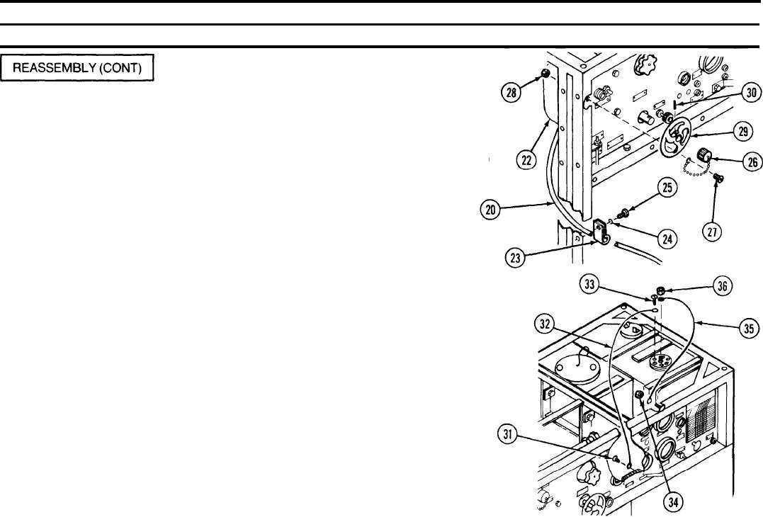
Loop clamp (23)
Slide loop clamp (23) around cable (20) and secure with flat washer (24)
Flat washer (24)
and hexagon head cap screw (25).
Hexagon head cap
screw (25)
Electrical connector
Screw electrical connector cover (26) onto HEATER RECEPTACLE AND
cover (26)
SWITCH socket on the alternator junction box (22). Secure the end of
Machine screw (27)
chain with machine screw (27) and hexagon head self-locking nut (28).
Hexagon head self-locking
nut (28)
NOTE
Handwheel may be held on with a drive pin.
Handwheel(29)
Slide handwheel (29) onto VALVE NO. 1 MANIFOLD stem and tighten
setscrew (30).
Setscrew (30)
Remove screw (31) from TB1-G and install wire (32). Remove machine
Screw (31)
Wire (32)
screw (33) with lock washer from fuel quantity transmitter flange. Insert
Machine screw (33)
machine screw (33) through terminal on end of wire (32) and reinstall
machine screw (33) with lock washer and tighten.
Nut (34)
Remove nut (34) from top screw securing the VACUUM GAGE. Attach
terminal lug on end of wire (35) to end of top screw and reattach nut (34).
Wire (35)
Remove nut (36) from center stud on fuel quantity transmitter and attach
Nut (36)
terminal lug on end of wire (35) to stud. Reattach nut (36) and tighten to
secure wire (35).

