T.O. 33B-1-1
5-48
5.3.4.3
Angle Beam DAC.
a. Connect the instrument and search unit to be used in the inspection. Turn the reject control to its
minimum position.
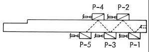
b. Use an IIW block. Place the search unit at P-1 as shown in Figure 5-52 and maximize the signal from
the flat-bottom hole face. Adjust the signal to bring the signal to 80% of saturation. Using a grease
pencil, mark the position of the signal peak on the display.
Figure 5-52. Search Unit Positions on IIW Block for Angle Beam DAC.
c. Position the search unit at P-2, P-3, P-4, and P-5. Without changing the gain, sweep, or sweep delay,
maximize the signal from the hole at each point.
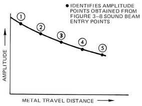
d. Mark the peak positions on the display. Draw a smooth curve between the points marked on the
display. Figure 5-53 shows a typical angle beam DAC curve.
Figure 5-53. Typical Angle Beam DAC Curve.
5.3.4.4
Surface Wave DAC.
DAC is usually not necessary for surface wave inspections, because the search unit can generally be moved back and
forth from a discontinuity to maximize the signal. If a DAC curve is needed for a surface wave inspection, it can be
easily established. The search unit is placed at a few points at different distances from the reference standard reflector.
At each point, the peak amplitude is measured and marked on the display. A smooth curve is then drawn through the
points as in the straight beam and angle beam procedures.
5.3.5
Transfer.
5.3.5.1
Description.
Transfer (attenuation correction) refers to methods used to compensate for differences in ultrasonic transmission
characteristics between the test part and the reference standard. For example, the surface condition of the reference


