T.O. 33B-1-1
5-43
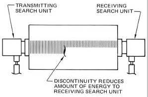
signal (see Figure 5-46). With this method, echoes from the discontinuities cannot be seen on the display. Therefore,
depth information on the discontinuities cannot be determined.
Figure 5-46. Through-Transmission Inspection.
5.3.3.1.3.1
NOTE
A major problem with through-transmission testing is maintaining alignment of the
transducers. Misalignment can reduce the amplitude of the received signal.
Anything causing the received energy to suddenly drop can be misinterpreted as a
defect.
The through-transmission method can be applied to thick materials, and is useful when insufficient energy is obtained
with the pulse-echo method. The through-transmission method can also be used to advantage on thin test parts when
the dead zone prevents a complete inspection with the pulse-echo method.
5.3.3.1.4
Applications.
The straight beam method is used to detect discontinuities with at least one surface oriented parallel to the test surface.
Typical discontinuity examples are laminations, corrosion, high-and low-density inclusions, porosity, forging bursts,
and cracks. Applications of the straight beam method depend upon the test part geometry.
5.3.3.2
Angle Beam Method.
5.3.3.2.1
General.
This method generally uses shear waves (paragraph 5.1.4.2) refracted in the test part at angles of 30 to 70 degrees.
5.3.3.2.2
Applications.
Angle beam methods are used extensively for field nondestructive inspection (NDI) and can provide for inspection of
areas with complex geometry or limited access. This is because angle beams can travel through a material by bouncing
from surface to surface. Useful inspection information can be obtained at great distances from the search unit. Angle
beam inspections are particularly applicable to inspections around fastener holes, inspection of cylindrical components,
examination of skins for cracks and inspection of welds (see Figure 5-47) shows typical angle beam inspections.