T.O. 33B-1-1
5-51
e. Note that in the above example, the metal travel distances to the back surface of the reference standard
and the test part were not equal. By using the DAC curve in establishing the transfer, this difference
was corrected.
5.3.5.3.2
Angle Beam Inspection for A Skin Crack.
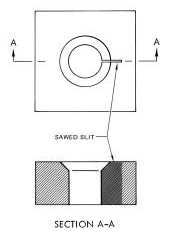
Use a reference standard configuration as shown in Figure 5-56. Reference standard should be same thickness and
material as skin to be examined. Specify size of saw cut. The inspection is set up using the saw cut to establish the
sensitivity. Any discontinuity having a signal exceeding 25% of the saw cut signal is cause for rejection. Transfer is
established as follows:
Figure 5-56. Reference Standard for Inspection for Cracks in Skin.
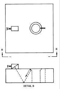
a. Place the search unit on the reference standard as shown in Figure 5-57 and position to obtain a
maximum signal from the top corner of the wall of the fastener hole. Adjust the gain to bring the signal
to 50% of saturation.
Figure 5-57. Positioning Search Unit for Establishing Transfer.
b. Place the search unit on the skin, and maximize the signal from the same size fastener hole as in the
standard by adjusting the position of the search unit. Do not change the gain setting used for the
fastener hole in the standard.


