T.O. 33B-1-1
5-49
standard and test part may differ, and/or the internal structures (grain size, etc.) may differ. Such differences cause the
signal from a discontinuity in the test part to differ from the signal from the same size discontinuity in the reference
standard. In order to obtain consistent results from ultrasonic inspections, it is necessary to correct for these differences
by using transfer.
5.3.5.2
General Procedure.
a. Transfer shall be accomplished by noting the dB or gain difference in the responses received from
reflectors in the reference standard and the part or piece of material to be inspected.
b. Use the echo signals from the same type of reflector in both the reference standard and the test part to
establish transfer. For example, use back surfaces, flat-bottom holes, side-drilled holes or "V" notches
(for angle beam inspections). If possible, a minimum of four reflections from different locations in the
part or piece of material to be tested shall be noted, and the lowest response shall be used for
comparison with the response from the reference standard. In practically all cases, any alteration of the
test part is prohibited. Therefore, transfer must be accomplished using reflectors already included in the
test part. Typical reflectors are the back surface or a fastener hole.
5.3.5.3
Examples.
5.3.5.3.1
Straight Beam Inspection of A Two- Inch Plate.
a. Suppose that a specification requires that any material with a discontinuity signal greater than the
signal from a 5/64- inch diameter FBH is unacceptable. The inspection is set up by establishing a DAC
curve in accordance with paragraph 5.3.4.2. Use ASTM blocks with 5/64-inch diameter FBHs and
metal travel distances of 1/8, 1/4, 1/2, 3/4, 1-1/2, and 3 inches. Assume the curve shown in Figure 5-52
is obtained. Note that the 1/8-inch point is not shown. This is because the dead zone extends beyond
1/8 inch. Note that the near field appears to end around 3/4 inch.
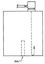
b. After constructing the DAC curve, the amount of transfer is established through use of back surface
reflections. The search unit is placed on the 1-1/2 inch metal travel ASTM standard as shown in Figure
5-54. This gives 2-1/4 inch metal travel to the back surface. The gain control is set to bring the back
surface signal to the DAC curve as shown in Figure 5-55. This gain setting is maintained, and the
search unit is placed on the test part. Assume the first signal shown in Figure 5-57 is obtained. This is
50% lower or 6 dB lower than the DAC curve at the 2-inch metal travel distance. This is the amount of
transfer; the amount by which the gain must be increased after calibration.
Figure 5-54. Search Unit on ASTM Block for Determining Transfer Amount.


