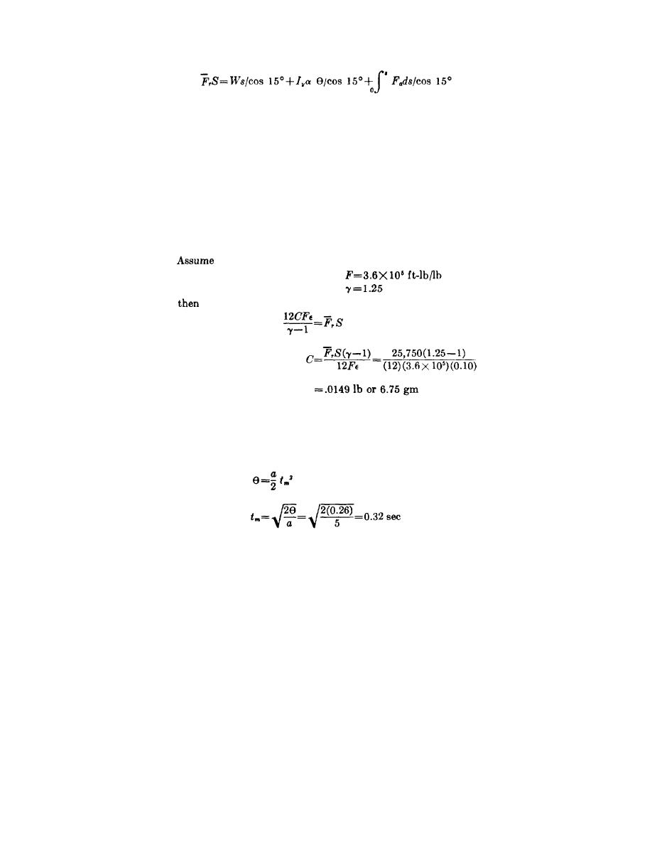
which, with simplification, gives the total energy output of the thruster (FTS).
Where:
θ = angle in radians through which the hatch moves.
The angle through which the hatch moves is 15 or 0.26 radian. Substituting the applicable figure
gives
FTS = 100(8)(1/cos 15+90(5)(.26)(1/cos 15+(1/2)(6,000)(8)(1/cos 15
)
)
)
FTS = 830+120+24,800=25,750 in.-lb
(e) Devices of this type usually operate at about 10 percent ballistic efficiency; therefore, the required
propellant weight may be estimated as follows:
(f) The thruster must overcome a high initial force which decreases as the stroke progresses; hence,
plateau propellant composition with regressive geometry (i.e., cord grains (uninhibited rod)) probably
are best for this application.
(g) If the angle (θ) through which the hatch moves is known, an approximate stroke time and propellant
burning time can be estimated.
This stroke time is conservative because it is based on an average acceleration of 5 rad/sec which is
actually the peak acceleration. The average would be somewhat lower.
52. Development of Propellant Charge Design. a. Grain Design.
(1) The basic problem in the selection of a propellant grain design for most stroking propellant actuated
devices is the requirement that gases must be supplied at an increasing rate during the functioning time of
the device. As noted earlier in this chapter, for most catapult applications a constant or even slightly
increasing pressure is desired after maximum acceleration has been reached. Due to (1) the increase in
internal volume as the stroke lengths, (2) the high heat transfer rate which causes a large loss of energy,
(3) gas leakage, and (4) energy transferred to the accelerated mass, an increasing rate of gas evolution
must be provided. Limiting this rate of gas production, however, is the maximum rate of change of
acceleration and the maximum acceleration allowable which
57


