TM 5-3740-214-14
ELECTRICAL PARTS GROUP (Continued)
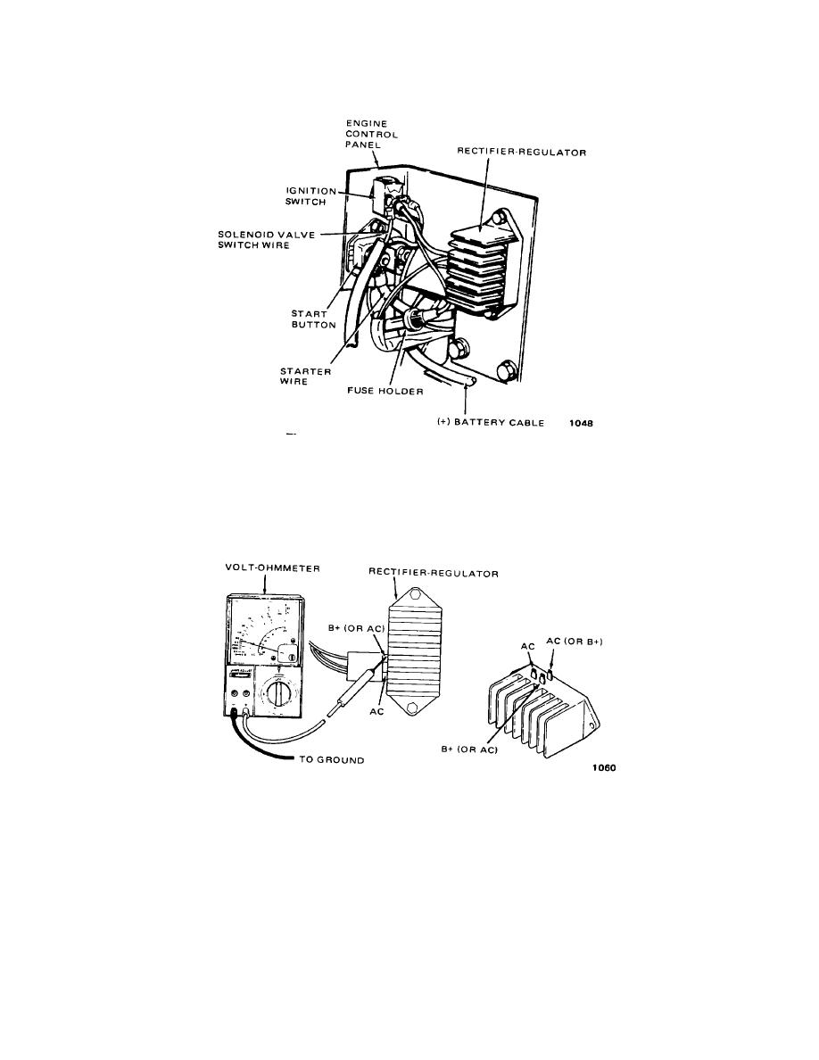
Figure 5-238. Engine Ignition Assembly
NOTE
The engine must be running while checking the rectifier-regulator.
Figure 5-239. Rectifier-Regulator Test
(a) Connect the negative (-) meter lead to a grounded engine part and the positive (+) meter lead to the B +
terminal at the rectifier regulator. Do not disconnect the rectifier-regulator wire. If the voltage is 13.8 volts or higher,
place a load of 5 amps or more on the battery to reduce the voltage.
If the charge rate increases, the rectifier-regulator is ok.
If the charge rate does not increase, go to Step b, below.
5-218


