TM 3-4730-200-15
c. The reporting of errors, omissions, and
d. Refer to TM 740-90-1 for administrative storage
recommendations for improving this manual by the
instructions on this equipment.
individual user is encouraged.
Reports should be
submitted on DA Form 2028 (Recommended Changes
to DA Publications) and forwarded direct to:
Commanding Officer, Edgewood Arsenal, ATTN:
Paragraph 4 deleted.
SMUEA-DE-ET, Edgewood Arsenal, Md. 21010.
SECTION II
USE AND DESCRIPTION
5. Use
containers, for venting 1-ton containers, for starting the
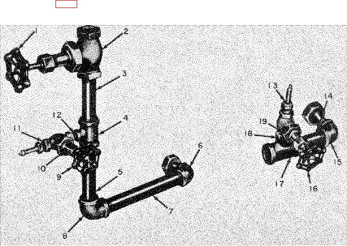
The line filling adapter (fig. 1) is used for adapting the
flow from partly filled 1-ton containers, and for clearing
M3 airplane smoke tank filling line to the valves in 1-ton
clogged tubes and valves.
A. VENTING ASSEMBLY
B. FILLING ASSEMBLY
1
Handwheel
11
Pneumatic tank valve
3
1
7
2
Globe valve ( /4-in.)
12
Pipe nipple ( /4- by /8-in.)
3
3
Pipe nipple ( /4- by 4-in.)
13
Pneumatic tank valve
3
3
1
4
Reducing pipe tee ( /4- by /4- by /4-in.)
14
Pipe nipple (- by 3-in.)
3
5
Pipe nipple ( /4- by 5-in.)
15
Angle valve adapter
6
Angle valve adapter
16
Handwheel
3
3
3
1
7
Pipe nipple ( /4- by 8-in.)
17
Reducing pipe tee ( /4- by /4- by /4-in.)
1
7
3
Pipe elbow ( /4-in. by 90)
18
Pipe nipple ( /4- by /8-in.)
8
1
19
Globe valve ( /4-in.)
9
Handwheel
1
10
Globe valve ( /4-in.)
B-Filling assembly
A-Venting assembly
Figure 1. M1 1-ton container line filling adapter.
AGO 5012A
3

