
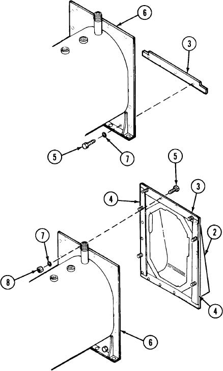
Position the bottom fire box gasket (3) with notched end facing upward
Boiler unit (6)
onto the boiler unit (6) and insert four machine screws (5) with internal
Internal tooth lock
tooth lock washers (7) through the boiler unit (6) and fire box gasket (3)
washers (7)
With two or more soldiers, lift the refractory box assembly (2) with gas-
Hexagon plain nuts (8)
kets, screws, and lining in place. Position it onto end of boiler unit (6) and
aline holes. Install remaining machine screws (5) through refractory box
assembly (2) and gaskets (3 and 4). Secure refractory box assembly (2) to
boiler unit (6) with remaining internal tooth lock washers (7) and hexagon
plain nuts (8). Check all the way around the edge of the refractory box
assembly (2) to make sure gaskets (3 and 4) are properly installed.
Tighten all machine screws (5) and hexagon plain nuts (8) equally.
TM 3-4230-209-30&P
2-231