
TM 3-4230-209-30&P
2-180
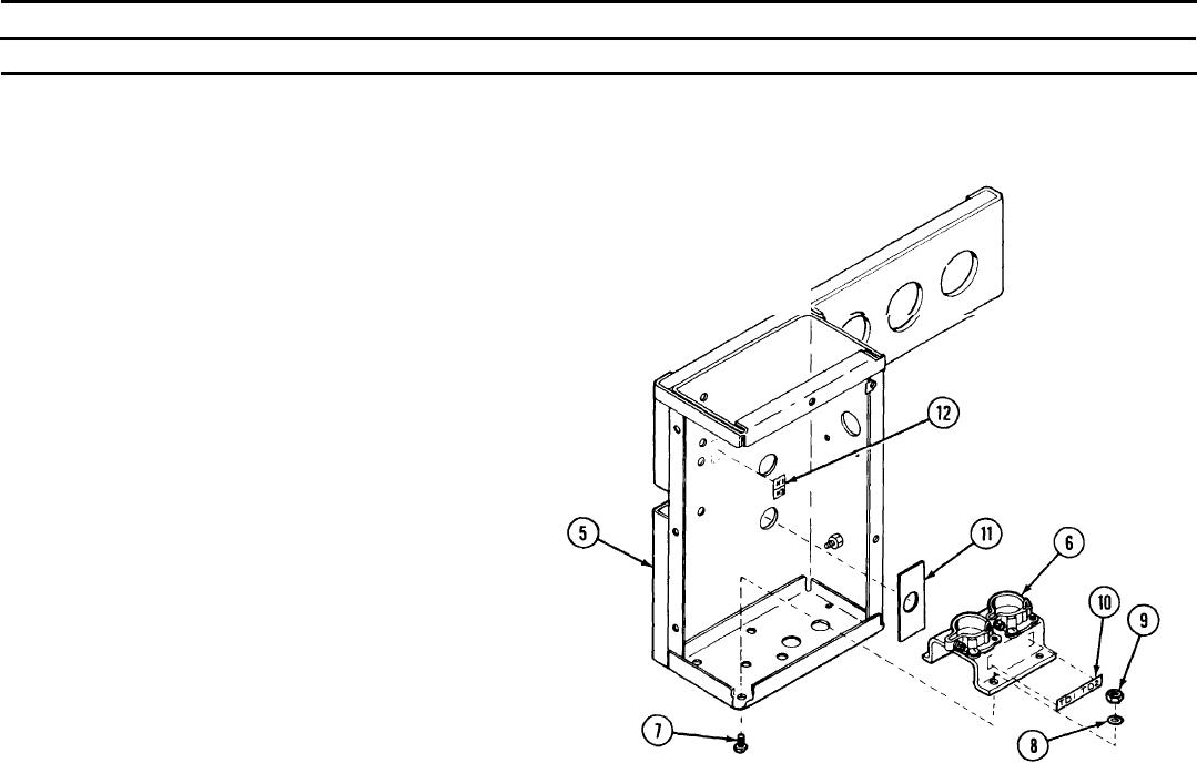
2-37. CONTROL BOX ASSEMBLY (CONT).
REMARKS
ACTION
LOCATION/lTEM
Control Box Assembly/
Position support (6) into control box (5) and aline the four holes. Insert
Machine screw (7)
four machine screws (7) up from the bottom through the control box (5)
Internal tooth lock
and support (6). Secure with four internal tooth lock washers (8) and
washer (8)
hexagon plain nuts (9).
Hexagon plain nut (9)
Install new thermal delay relay identification plate (10), switch
Thermal delay relay
identification plate (10)
identification plate (11), and relay identification plate (12) if removed.
Switch identification
plate (11)
Relay identification
plate (12)