
TM 3-4230-209-30&P
2-176
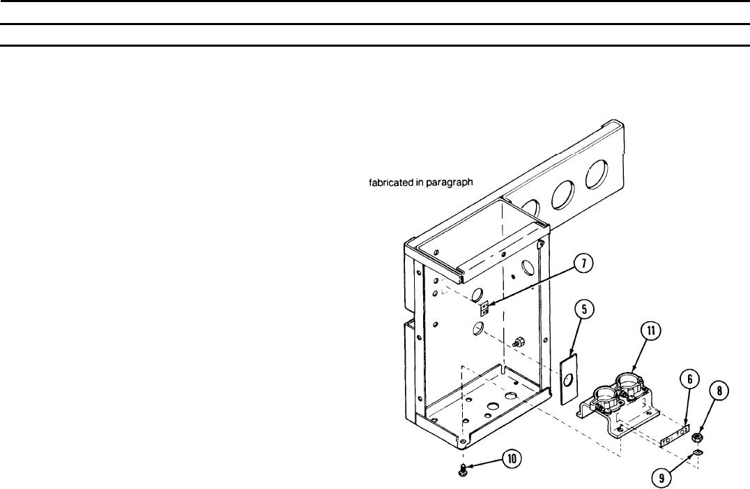
2-37. CONTROL BOX ASSEMBLY (CONT).
REMARKS
ACTION
LOCATION/lTEM
DISASSEMBLY (CONT)
Control Box Assembly/
Scrape off and discard switch identification plate (5), thermal delay relay
Switch identification
identification plate (6), and relay identification plate (7) only if damaged.
plate (5)
Thermal delay relay
Remove four hexagon plain nuts (8), internal tooth lock washers (9), and
identification plate (6)
machine screws (10). Remove support (11).
Relay identification plate (7)
Hexagon plain nut (8)
Remove wiring from support (11). Wires will be
Internal tooth lock
2-43.
washer (9)
Machine screw (10)
support (11)