
TM 3-4230-209-30&P
2-120
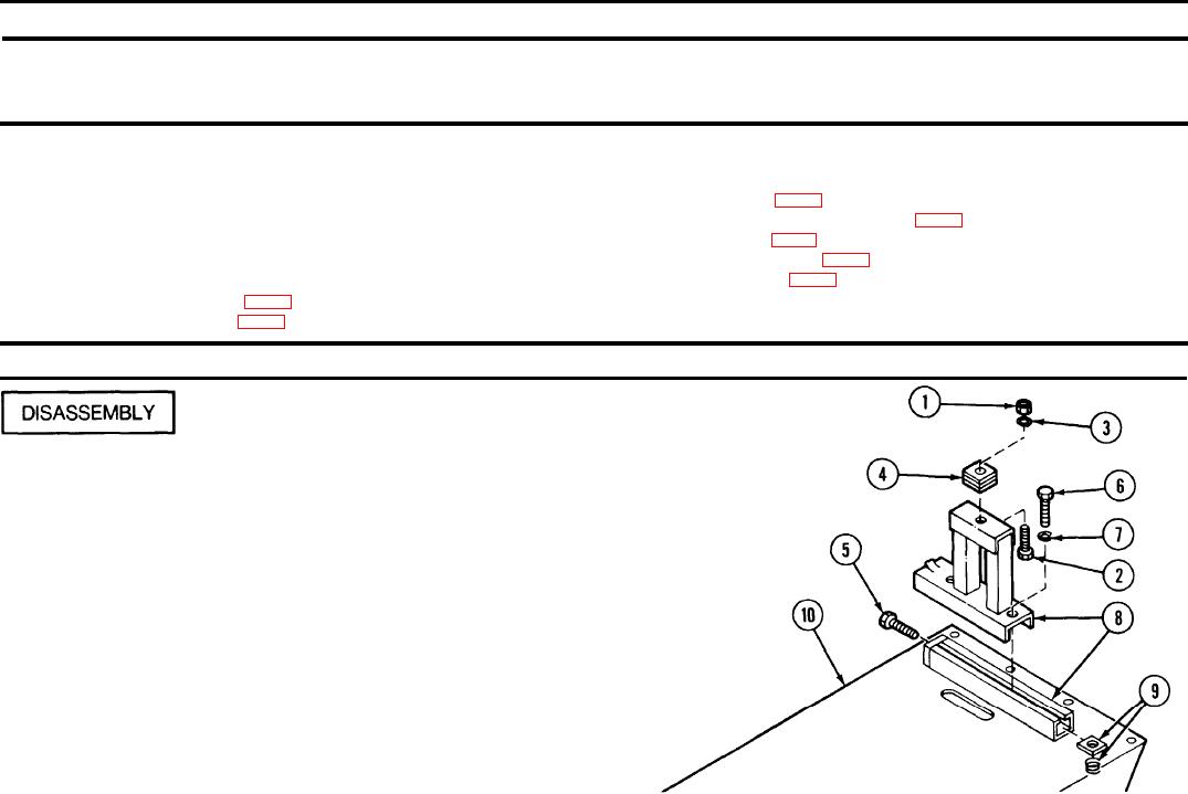
2-26. PUMP BASE SKID, ENGINE MOUNT 1, ENGINE MOUNT 2.
This task covers:
c. Reassembly
a. Disassembly
b. Repair
INITIAL SETUP
Wiping rag (item 31, app C)
Tools and Special Tools
Chassis and running gear brush (item 5, app C)
Automotive Maintenance and Repair Field Maintenance
Paint brush (item 6, app C)
Shop Equipment, Basic, Less Power (SC 4910-95-CL-A31)
Scratch wire brush (item 7, app C)
Abrasive cloth (item 9, app C)
Materials/Parts
Polyurethane coating (item 29, app C)
Dry cleaning solvent (item 14, app C)
REMARKS
ACTION
LOCATION/lTEM
Pump Base Skid, Engine
Mount 1 Engine Mount 2/
Unscrew and remove hexagon self-locking nut (1), hexagon head cap
Hexagon self-locking nut (1)
screw (2), flat washer (3), and shock mount pad (4).
Hexagon head cap
screw (2)
Flat washer (3)
Shock mount pad (4)
Remove machine bolt (5), two hexagon head cap screws (6), and lock
Machine bolt (5)
washers (7). Remove moveable part of channel assembly (8). Do not
Hexagon head cap
remove the two sets of nuts (channel clamping style) (9), or the stationary
screw (6)
part of channel assembly (8) welded to the skid base (10) unless they
Lock washers (7)
need to be replaced.
Channel assembly (8)
Nut (9)
Skid base (10)