TM 10-5410-228-24
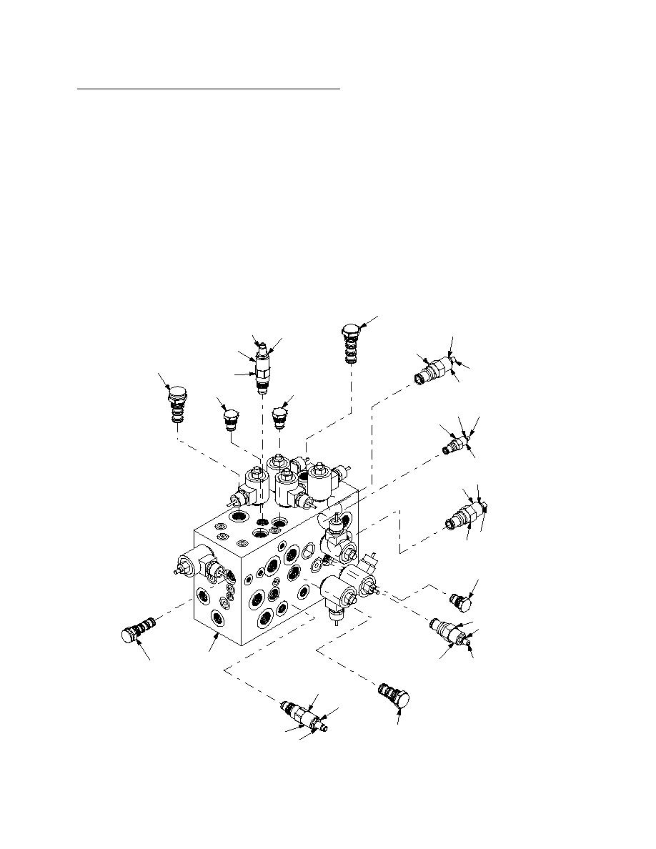
2.14.5 Hydraulic Manifold Valve Replacement Continued.
(13) If amp draw is incorrect, remove plastic cap from hydraulic pump control valve (7). Loosen
large, outer locknut on hydraulic pump control valve (7). Rotate entire barrel less than one half
turn to obtain 24.5 amps (maximum) on meter. Tighten locknut.
(14) Set ESS MODE selector switch to COOL, NBC FAN switch should be OFF.
(15) Loosen small locknut on hydraulic pump control valve (7). Using 3mm hex key, adjust allen
screw to obtain 24.5 amps (maximum).
(16) Set NBC FAN switch ON. Observe any amperage change on meter.
(17) Loosen large locknut on hydraulic pump control valve (7). Rotate entire barrel less than one half
turn to obtain 24.5 amps (maximum) on meter. Tighten locknut.
(18) Repeat steps 13 through 17 to obtain 24.5 amp (maximum) draw in both NBC modes.
NOTE
It may not be possible to adjust to 24.5 amps in both NBC modes. After several attempts,
adjust to 24.5 amps in VENT mode, then adjust in COOL mode as close to 24.5 amps as is
possible without exceeding 24.5 amps in VENT mode.
FP3
9
15
8
RD1
3
PD1
16
2
FP2
CV1
CV2
18
17
4
FP6
FP5 15
16
3
CV3
3
15
1
16
FP1
SL1
2
8
244-1-M
LS3
RD2
9
2-302


