TM 10-5410-228-24
1.16 HYDRAULIC SYSTEM Continued.
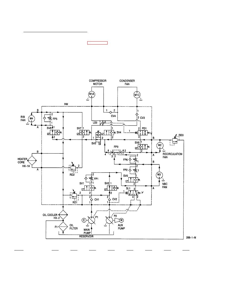
When the hydraulic circuit is in heat mode (figure 1-17) and air beam pressure is reduced to 1.5 psi for any
reason, the rib fan motor, M4, is automatically turned on. This is accomplished by applying +24 Vdc to the
coils of solenoid valves SV2, SV5, SV7, SV8, and SV9. SV2, SV5 and SV8 are opened and SV7 and SV9 are
closed. This diverts the hydraulic fluid flow away from the heating coil, HX-1A, and takes the path of less
resistance through the rib fan motor, M4. The speed of the rib fan is controlled by flow control FP5 which
diverts hydraulic fluid flow around the rib fan motor to limit its speed and pressure for safety. When air
beam pressure is increased to 2.9 psi, the system is returned to the previous condition.
Valve
SV1
SV2
SV4
SV5
SV6
SV7
SV8
SV9
Energized State
OFF
ON
OFF
ON
OFF
ON
ON
ON
Position
Closed
Open
Closed
Open
Closed
Closed
Open
Closed
Figure 1-19. Static Mode, Internal Power, Heat Mode, Rib Fan On, Full NBC


