TM 10-5410-228-24
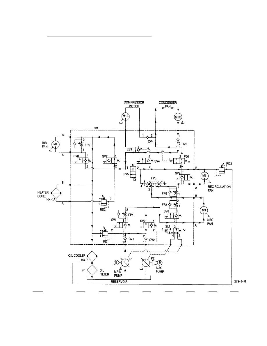
Placing the control switches in the positions corresponding to the above modes opens solenoid valve SV2 and
closes solenoid valve SV9 by applying +24 Vdc to the coils. All remaining solenoids remain in their normal
de-energized positions. The engine driven pump, through a combination of gravity and suction, draws fluid
from the hydraulic reservoir in the ECU and supplies pressure to the hydraulic control manifold. Fluid flows
through the manifold and is then routed to the vent (NBC) fan, M3. The fluid is returned to the manifold
where it is divided by flow control, FP3. Part of the fluid is supplied to the recirculation fan, M2, and the
balance is diverted around the motor in order to maintain proper speed control. The fluid flows through the
condenser fan motor, M1C. The total fluid flow is routed through solenoid valve SV7, then passes through
the oil cooling heat exchanger. During VENT mode, the air flow action created by the condenser fan draws
air over the heat exchanger, cooling the hydraulic fluid. From there the fluid is routed to the reservoir
mounted filter and returned to the reservoir.
SV1
SV2
SV4
SV5
SV6
SV7
SV8
SV9
Valve
Energized State
OFF
ON
OFF
OFF
OFF
OFF
OFF
ON
Position
Closed
Open
Closed
Closed
Closed
Open
Closed
Closed


