T.O. 33B-1-1
6-96
6.8.11.5
Illuminators.
The illuminator must provide sufficient light to transmit adequate light for the observer to distinguish areas easily.
Since the human eye has greater visual acuity and contrast visualization at given levels of light, then the illuminator
must provide control of light levels to adjust for optimum visual response of observer. The accepted differential of
density detectable by the average individual is 0.02. Thus, a 2 percent change in thickness must result in density change
of 0.02 or more. The contrast sensitivity of the human eye is greatest when light reaching the eye comes from one
source. Therefore radiographs should be read in areas of subdued light to avoid reflection and glare. The eye responds
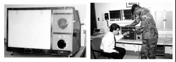
best if all the light reaching it is of approximately the same brightness (see Figure 6-44). The ASTM standard on
illuminators is cited in Ref. 15.
Figure 6-44. Typical High Intensity Viewer.
6.8.11.5.1
Opaque masks to suit the size of radiographs to be viewed and to isolate areas of interest SHALL be used to avoid
brightness around edges of film, excess light from low density areas of no interest and reduce light intensity from the
illuminator when changing radiographs. This prevents the eye from continually adjusting itself to the changing light
levels that cause fatigue. At normal light levels the eye can see the differences in light brightness of two percent. As
light reaching the eye decreases, the percentage increases radiographs having great ranges of density and complicated
image patterns should be viewed on high intensity, 14 x 17 illuminators having adjustable diaphragms and variable
light intensity to assure best eye response.
6.8.12
Reading Radiographs.
Interpretation of radiographic images cannot be translated into mathematical formulas or routine procedures. The wide
variety of test objects and the various fabrication processes by which they have been made makes radiographic
interpretation a complex subject. Radiographic inspection is conducted to assure that a material or part has the
required integrity to reliably perform the function for which it was designed. This does not mean perfection. All parts,
materials, and processes are imperfect. Therefore, the purpose of radiography is to determine the degree of
imperfection. The effects of discontinuities or manufacturing deviations must be correlated with the function of the
part. Specifications are usually used to spell out the discontinuities that may be considered detrimental to the function
of the part and the acceptable magnitudes of the discontinuities. It is the duty of the film interpreter to recognize the
various discontinuities, their magnitudes, and be capable of relating them to the particular specification required. The
responsibility and capability of the radiographic interpreter cannot be over emphasized. Often many human lives and
investments of millions of dollars are depending on the judgment of the radiographic interpreter. Any information that
can be of assistance in making a judgment of discontinuities should be fully utilized. Interpretation of the shadow
images visible in the radiograph is an acquired skill and there is no substitute for experience. Experience aids the film
reader in recognizing discontinuities and in identifying where they can be expected to occur in a particular part or
structure. The mistakes in radiographic interpretation most often are a result of misreading film artifacts. There are a
number of density patterns that resemble welding and casting defects that are often unjustified causes for rejects.
Processing and handling errors that affect radiographs and can be misinterpreted are listed in Table 6-21. A good
check is to look at the surface of the film by reflected light to observe any unusual patterns.


