T.O. 33B-1-1
4.5.5.9
Detection of Cracks Under Metallic Coatings.
The detection of cracks under metallic plating and coating is similar to detection of subsurface f laws. The
magnitude of the total response consistently decreases with increasing coating thickness. With meter type
instrumentation with a constant frequency test system, the thickness of plating or coating through which
cracks can be detected decreases with increasing plating conductivity and/or magnetic permeability. In
general, decreasing frequency permits detection of larger cracks under thicker coatings because of the
increased depth of penetration. Detection of cracks under metallic coatings with phase analysis instrumenta-
tion using the impedance plane diagram can be performed with more accuracy and sensitivity than with
meter instruments because phase information can be measured. Recent research has shown that multifre-
quency eddy current systems may find application for detecting and measuring cracks under metallic
coatings.
4.5.6
Effects of Scanning Techniques on Detection.
4.5.6.1
Inspection Technique.
Consistent positioning of the probe in relation to edges and interfaces during calibration and scanning should
be established to ensure maximum response from f laws with minimum interference from other sources of
indications. If conditions are known to exist which may result in false indications or which could mask true
indications from f laws, these conditions should be noted in the procedure and a means of interpreting or
evaluating the false indications provided. In performing eddy current inspection of an area, the distance
between scans or between measurements must be selected to ensure complete coverage for the minimum size
f law or variation in properties to be detected. In determining maximum distance between scans, considera-
tion must be given to the change in magnitude of f low response as the probe coil center position increases in
distance from the center of the crack.
4.5.6.2
Scanning Speed.
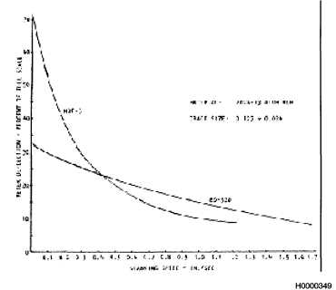
The scanning speed employed in eddy current inspection for cracks is related to the type of equipment utilized
and the inspection technique. Slowest scanning speeds are necessary when the inspector is required to read a
meter while manually directing the probe in the specified scanning pattern. The rate of scanning is primarily
determined by the damping of the instrument meter. Meter damping prevents excessive vibration and
oscillation of the meter needle and provides errors in instruments readings. The damping effect reduces the
Figure 4-46.
Effect of Scanning Speed on Meter Deflection from a Crack
Change 3
4-57


