T.O. 33B-1-1
4-55
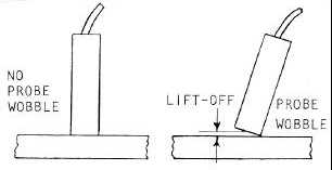
shown in Figure 4-44. The amount of lift-off obtained because of changes in probe angle depends on the diameter and
shape of the probe tip. Rounded tips of small diameter cause less lift-off than flat tipped probes with larger diameters
or impedance display instruments, lift-off effect can be lessened by changing the vertical to horizontal sensitivity ratio.
Figure 4-44. Lift-Off Resulting from Probe Wobble.
4.5.5
Effects Of Crack Location On Detectability.
4.5.5.1
Crack Location And Orientation.
To provide the optimum sensitivity and reliability for crack detection, the maximum information should be available
regarding the expected crack. Often, this information is provided from previous history of cracks in the designated
locations. In other cases, such information may be determined from knowledge of stress distribution during service.
Increasing definition of crack location and orientation permits the inspector to reduce his inspection time. For manual
eddy current inspection, reduction in scanning time provides less operator fatigue and consequent improvement in
inspection reliability.
4.5.5.2
Cracks At Part Edges.
The edge of a part can be represented as an infinitely large crack and, consequently, produces a strong signal during
eddy current inspection. The problem in inspecting part edges for cracks is separation of crack response from the
strong edge response (edge effect).
4.5.5.3
Inspection At Part Edges.
Two approaches can be used to inspect for cracks at part edges. The first method is to null the instrument with the
probe at the edge of the part. Then, usually with a non-conductive fixture or some other method, the probe is
maintained at the edge as it is scanned along the edge. If this position can be maintained, the inspection can be done
with greater sensitivity than is possible with the same instrument and probe away from the edge. The second approach
is to use a shielded probe, thus minimizing response from edges.
4.5.5.4
Fixtures And Holders For Edge Inspection.
One of the simplest methods for eddy current inspection adjacent to a linear edge of a part is to tape or hold a straight
edge at a predetermined distance from the edge. Nonmetallic straight edges should be used for this purpose. A simple
fixture which can assist in positioning the probe adjacent to an edge is shown in Figure 4-45. This fixture maintains
the probe center 1/8 inch from the edge, but closer edge inspection can be obtained by varying the position of the drilled
hole.


