T.O. 33B-1-1
4-4
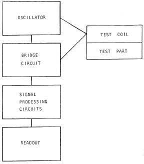
Figure 4-2. Block Diagram of Eddy Current Inspection System.
4.1.10.3
Bridge Circuit.
The bridge circuit converts changes in eddy current magnitude and distribution into signals that are ultimately
processed and displayed. A common mode of operation is to have the output of the bridge equal zero for a “good” or
‘“non-flaw” condition. Presence of a flaw or an “other-than-good” condition results in an unbalance of the bridge, thus
producing a relatively small signal. This signal becomes the input to subsequent circuits.
4.1.10.4
Signal Processing Circuits.
The processing of the signal from the bridge circuit depends on the type of information to be displayed. Simple eddy
current devices can be built which detect and amplify the signal or convert the signal into digital format (i.e., a
conductivity value). More sophisticated systems can process the complex electromagnetic signal into signal amplitude
and signal phase, and provide filtering to suppress unwanted signals. Details of the processes are discussed further in
later sections.
4.1.10.5
Output Display.
Eddy current test data can be presented as an analog or digital meter readout, a strip chart, an X-Y recorder plot, an
oscilloscope display or a video screen presentation. Meters are suitable for performing specific types of tests such as
crack detection, alloy sorting, coating thickness, or other types of testing that require a measurement of signal
amplitude only. Strip charts, X-Y recorders and digital storage allow the signal amplitude to be displayed and
correlated with some other parameter such as time or position. Eddy current instruments with a 2 dimensional
graphical display are used where both the eddy current signal amplitude and phase must be measured. These are
becoming the most common instruments available and provide the inspector with the greatest capability in interpreting
the results of an eddy current inspection. They are also very portable and can be battery operated, but are a few pounds
heavier than those with a meter display.
4.1.11
Limitations of Eddy Current Method.
There are several limitations to the eddy current inspection method. First, it is limited to electrically conductive
materials or materials with electrically conductive components such as carbon fiber re-enforced composites. Second,
flaws parallel to the surface inspected are difficult to detect. The most serious limitation, however, is the necessity to be
able to prevent or suppress eddy current responses to non-flaw conditions. This becomes a particularly difficult
problem with ferromagnetic materials.


