TM 5-6635-386-12&P
Seating area requirements for the transmission mode
comprise only a 2 x 6-inches wide surface under the GM
tube, thus the tester can be used on very difficult
surfaces where a backscatter tester would be impossible
to use.
Transmission surface roughness error is approximately
1/10th that of the backscatter errors.
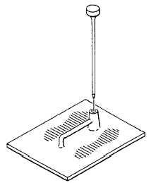
1-18. DRILL TRANSMISSION HOLE
The transmission hole must be vertical to the smoothed
surface and must not be damaged in the process of
drilling and retraction of the drill.
Place the Cast Guideplate on the surface and use the
guide to support the drill pin. Hammer the drill pin into
the ground, tap it lightly to loosen it, twist it to further
loosen it, and pull it out of the ground.
WARNING
Do not use the cast guideplate as a retraction
device. It will damage the top of the guide hole.
Figure 1-6. Transmission Hole
NOTE
During drilling and retraction, the operator’s weight on the
guideplate confines the soil to prevent eruption or
puffing.
The operator’s weight on the plate confines the soil in
drilling and in retraction to produce a neat, undamaged
hole for the readings.
On heavily compacted material above 95%, cracks may
appear in the soil. These will not affect the readings if
the tester is placed so no crack extends from the source
directly back to the detector tubes.
If the drill pin "walks away" as a result of striking a rock in
the soil, try another location. If repeated tries cannot
produce a satisfactory hole, then the test should be
aborted.
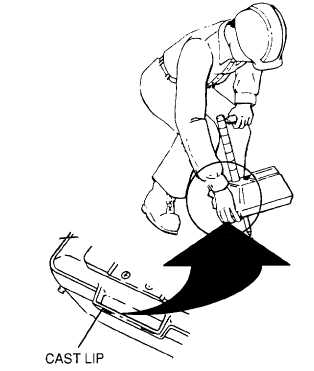
1-19. SEATING THE TESTER IN TRANSMISSION
From a radiation exposure standpoint, it is undesirable to
have to spend a great deal of time "playing" with the
tester in seating it. Locating the hole for insertion of the
source rod in transmission is frequently a problem and
CPN has made this easy for the operator.
Figure 1-7. Positioning Source in Prepared Hole
A small cast lip (Fig. 1-7) is on the front of the bottom
casting to provide for insertion ease.
1-15