TM
3-6665-316-12
REPLACEMENT O F T R A N S M I T T E R T O N E M O D U L E ( c o n t i n u e d )
4-10.
2.
Carefully aline pins on tone module with holes in socket XZ1. One
pin has been removed from tone module, and corresponding hole in
This allows tone module to be installed
socket XZ1 has been filled.
only one way.
Push
tone
module
down
into
socket
XZ1
until
pins
are
fully
seated.
3.
4.
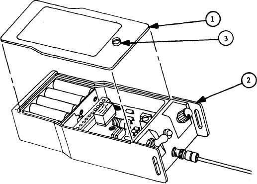
Mount
cover
(1)
on
chassis
(2).
5.
Turn
screw
(3)
down
until
snug.
Do
not
over-tighten
screw.
6.
Turn
over
so
GROUP/UNIT
identification
plate
(4)
is
up.
7.
If first three digits of replacement tone module SERIAL number (5)
do not match GROUP digits (6) recorded on transmitter GROUP/UNIT
identification plate (4), record first three digits of replacement
Record last digit next
tone module SERIAL number next to word GROUP.
Make sure digit recorded next to UNIT is a 5.
to UNIT (7).
NOTE
Grease pencil markings can be rubbed off to
make corrections to digits recorded on trans-
mitter.
4-18

