TM 3-6665-302-34
of replacement switches before installation.
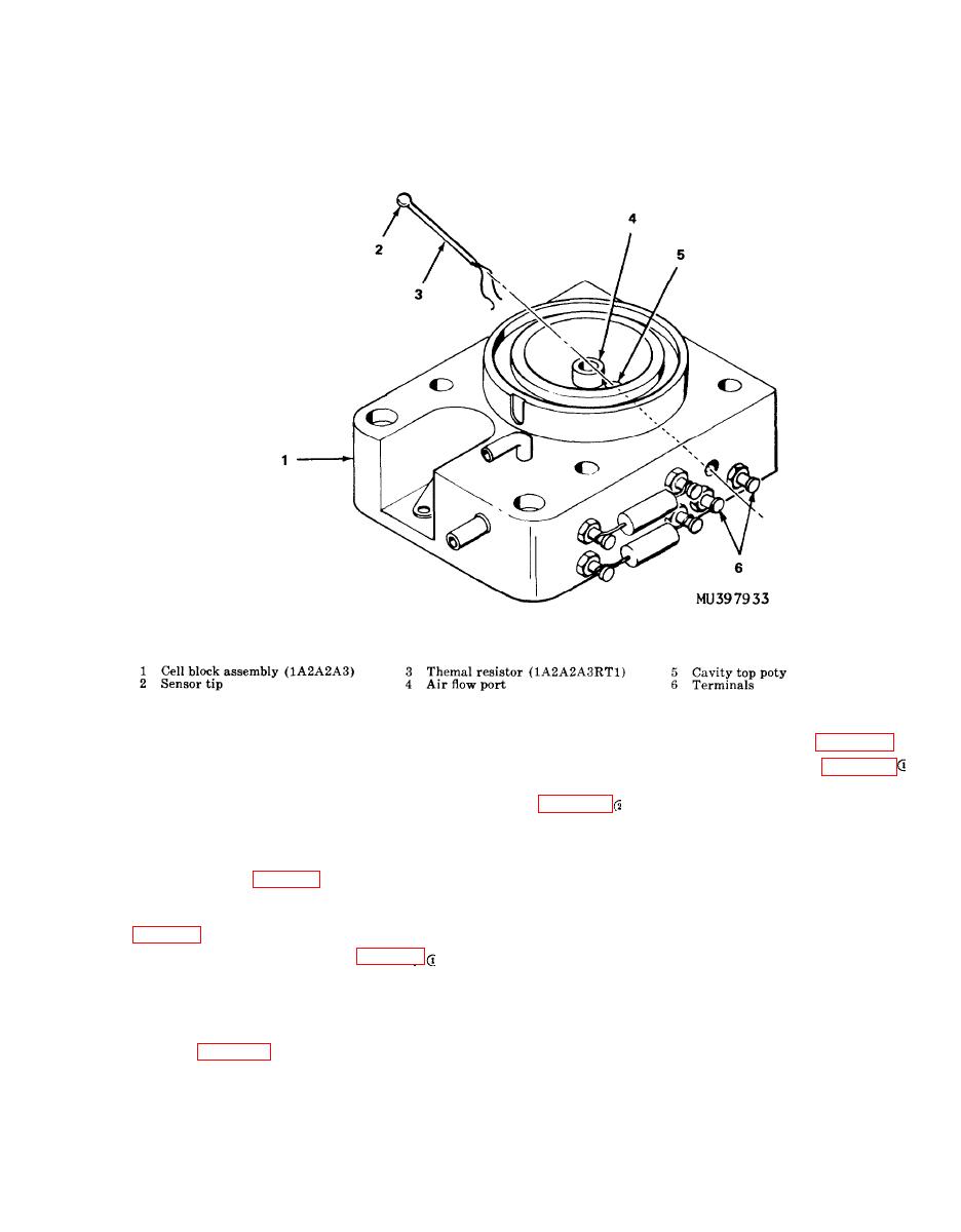
(1) Remove chassis assembly (para 3-36).
Switch (9) indicates an open circuit between
(2) Disconnect tubing (11, fig. 3-21 )
terminals at 50 F. or greater. Switch (10) in-
and tubing (21) from cell block assembly (75,
dicates a closed circuit between terminals at
fig. 321 ).
42 F. or greater.
(3) Remove preformed packings (37 and
(2) Position switches with TEMP SIDE
38) from cell block assembly (75).
against chassis subassembly (56).
(4) Remove sealing compound from elec-
(3) Using fig. 3-1 as a guide solder wires
trical connector of cell block assembly (75) un-
to applicable switch terminals. Coat soldered con-
til soldered connections are exposed.
nections with sealant from coating kit (item 6,
(5) Remove screws (78 and 71).
(4) Insert screw (22, fig. 3-21 ) through
(6) Pry cell block assembly (75) from chas-
chassis assembly and attach lockwasher (8),
sis subassembly (56). Tilt cell block assembly
washer (7), and thermostat retaining bar (6).
(75) until terminals on side are accessible.
Tighten screw (22).
(7) Unsolder wires from terminals.
(5) Install chassis assembly to case top as-
b. Installation.
sembly (para 3-37).
(1) Insert preformed packing (38) around
inner circular portion of cell block assembly
(75).
a. Removal


