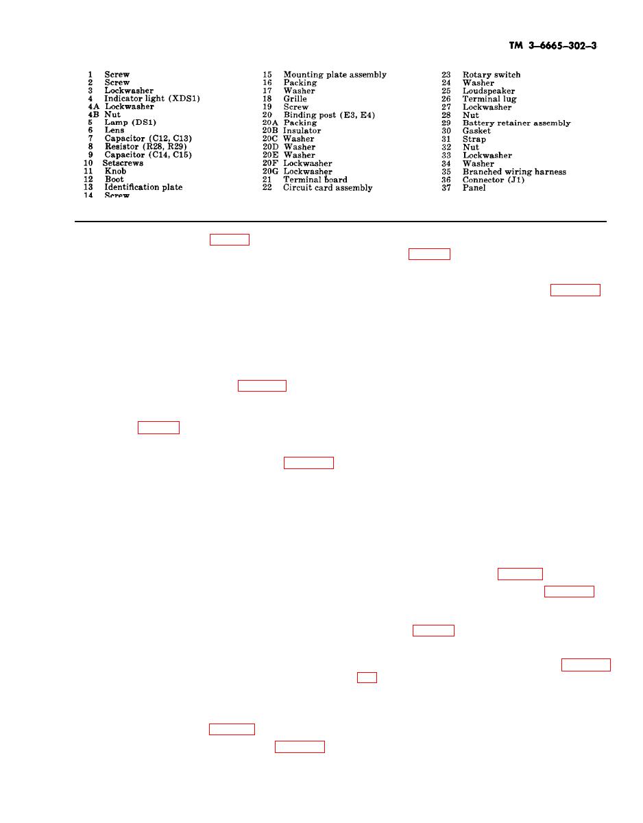
Figure 326. Panel assembly, exploded view -- Continued
(2) Remove screw (2, fig, 3-26) and lock-
3-69. Terminal Board
washer (3).
(3) Pull circuit card assembly (22) from
a. Removal.
connector (36).
(1) Disassemble M42 alarm unit (para 3-
b. Installation.
62).
(1) Insert circuit card assembly (22) in
(2) Unsolder capacitor (7 and 9) from
connector (36) with component-side facing loud-
terminal board (21).
speaker (25).
(3) Unsolder resistors (8) from terminal
(2) Install screw (2) and lockwasher (3).
board (2) and binding posts (20).
Tighten screw (2).
(4) Remove nut (20G), lockwasher (20F)
(3) Assemble M42 alarm (para 3-63).
and washer (20E). Washer (20D) and terminal
board (21) will fall free.
3-68. Binding Posts
b. Installation.
(1) Install washer (20D) axial terminal
a. Removal.
board (21) on ends of binding posts (20). Install
washer (20E), lockwasher (20F), and secure
(1) Disassemble M42 alarm unit (para 3-
with nut (20G).
62).
(2) Connect resistors (8) between binding
(2) Unsolder resistor (8) from bottom of
posts (20) and terminals of terminal board (21)
binding post (20) (view B).
as shown (view B).
(3) Remove nut (20G), lockwasher (20F),
(3) Connect and solder capacitors (7 and 9)
and washer (20E).
as shown (view B).
(4) Remove binding post (20), packing
(4) Coat all soldered connections with seal-
(20A), insulator (20B), and washer (20C) from
ant from coating kit (item 6, table 11).
panel (37). Washer (20D) will fall free.
(5) Assemble M42 alarm unit (para 3-63).
b. Installation.
(1) Position washer (20D) between term-
3-70. Rotary Switch and Boot
inal board (21) and panel (37).
(2) Install packing (20A), insulator (20B),
a. Removal.
and washer (20C) on binding post (20). Install
binding post (20) through top of panel (37),
(1) Disassemble M42 alarm unit (para 3-
washer (20D), and terminal board (21). Secure
with lockwasher (20F) and nut (20G).
(2) Tag and unsolder wires from terminals
of switch (23).
(3) Solder resistor (8) to bottom of binding
post (20). Coat soldered connection with sealant
(3) Loosen setscrews (10) and remove knob
from coating kit (item 6, table 11).
(11).
(4) Assemble M42 alarm unit (para 3-63).
(4) Unscrew and remove boot (12).


