TM 3-6665-302-34
1A2A2R8, and 1A2A2R7 are located in the detector
from the pump assembly (1A2A1.) preventing further
unit assembly. This string of series resistors parallels
operation until the M43 detector unit is reset.
heater (lA1HR1) and conducts whenever thermos-
b. When there are no chemical agents in the
tatic switch (1A2A2S1) is closed. The power dissi-
atmosphere, motor (1A2A1B 1) operates continu-
pated by the resistors warms the detector unit
ously. Power is applied to voltage regulator
assembly. Series resistors 1A2A2A3R2, 1A2A2R6,
(1A2A1A1) as long as the temperature within the
1A2A2R9, 1A2A2R2, and 1A2A2A5R2 parallel
M43 detector unit case keeps thermostatic switch
1A1HR2. When 1A2A2S1 closes and an M253
(1A2A2S2) closed. When the M43 detector unit is first
wintcrization kit is connected, the resistors conduct,
connected to a 24-volt dc power source and the
adding additional heat to the detector unit assembly.
temperature within the case is below 32 F.,
c. Thermal resistor (1A2A2A3RT1) senses the air
thermostatic switch (1A2A2S2) is open, and thermos-
temperature and causes the air inlet heater assem-
tatic switch (1A2A2S1) is closed applying power to
bly (1A2HR1) to operate when the ambient air
heater (1A1HR1). When the temperature within the
temperature is +90 F. or lower. This action warms
M43 detector unit reaches +40 F., thermostatic
the air drawn into the M43 detector unit.
switch (1A2A2S2) closes, causing motor (1A2A1B1) to
d. In temperatures of +32 F. and below, thermos-
operate. Thermostatic switch (1A2A2S1) alternately
tatic switch (1A2A5A1S1) closes causing current to
opens and closes to maintain proper operating
flow through heater 1A2A5A1HR1. The heater
temperature. Resistors 1A2A2R5, 1A2A2R4,
prevents icing at the AIR OUTLET PORT.
1A2A2R3, 1A2A2A5R1, 1A2A2R1, 1A2A2A3R1,
Section Il. M42 ALARM UNIT
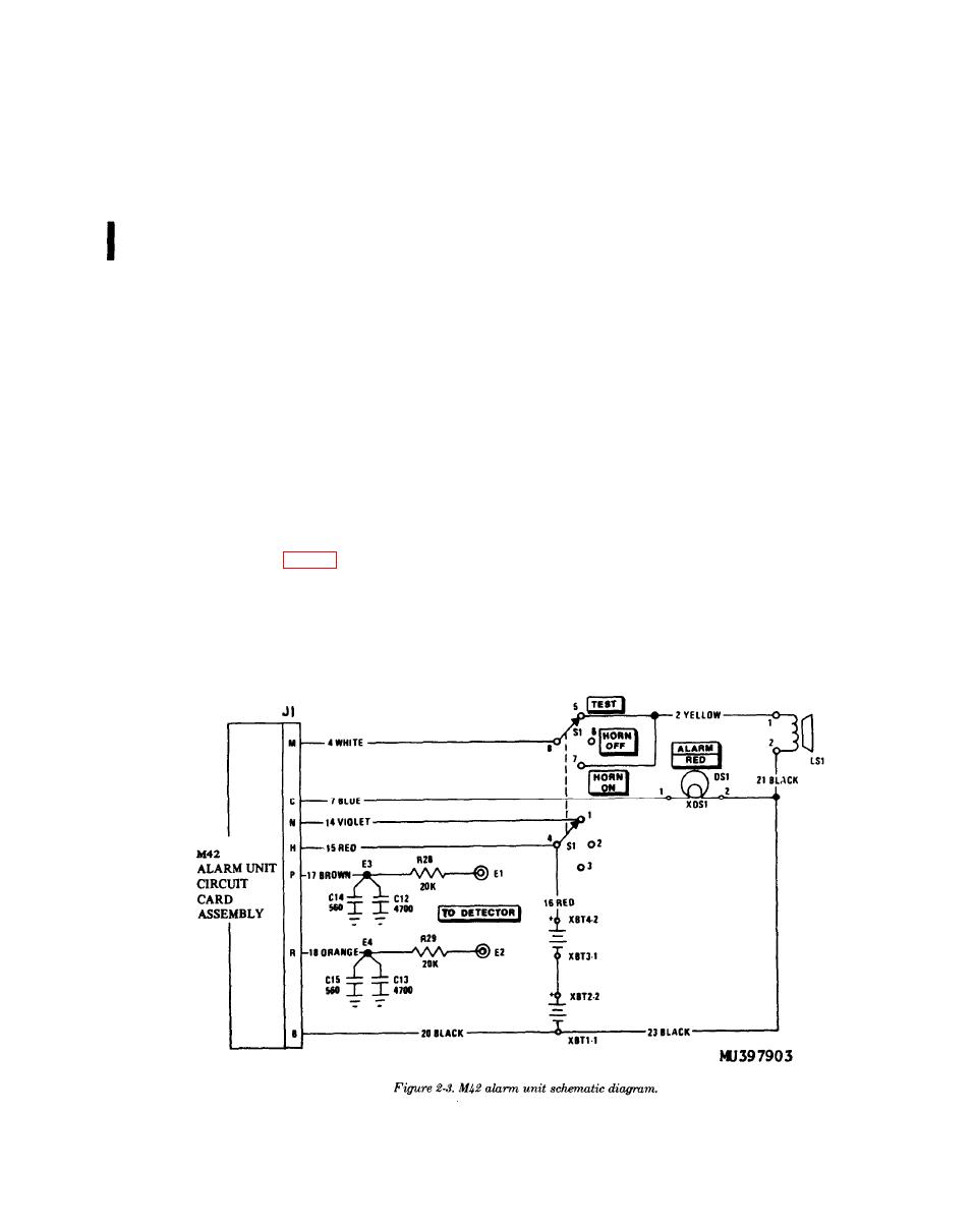
2-3. General
The alarm signal from the M43 detector unit is
Whenever the horn on the M43 detector unit is
applied through a pair of field wires to binding posts
triggered into operation, power is applied to the
E1 and E2 marked TO DETECTOR. The signal is
REMOTE binding posts on the M43 detector unit. If
then applied to the M42 alarm unit circuit card that,
the M42 alarm unit (fig. 2-3) is connected to the
in turn, triggers the loudspeaker (LS1) through
REMOTE binding posts of the M43 detector unit, the
switch (S1) and lights the ALARM RED indicator
M42 alarm unit will also be triggered into providing a
(DS1).
warning.
NOTE: 1. ALL RESISTANCE VALUES IN OHMS.
2. ALL CAPACITANCE VALUES IN UUF.
Change
2


