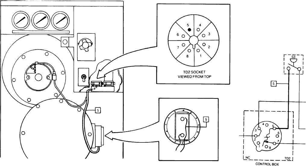
Step 5. Check wire No. 5 for continuity using the following procedures:
a. Remove thermal delay relay tube TD2 from its socket. Disconnect wire No. 5 from combustor air pressure switch S3.
b. Use multimeter to check for continuity between ends of wire No. 5 while it is being flexed. Stick one multimeter probe into thermal delay relay
TD2 socket, hole 5, and the other multimeter probe to end of wire No. 5.
Reinstall wire No. 5 back onto combustor air pressure switch S3 if continuity is indicated, and reinstall thermal delay relay tube TD2.
Replace wire No. 5 in socket base of TD2, hole 5, and attach the combustor air pressure switch S3 if anvthina other than continuity is
indicated. Reinstall thermal delay relay TD2 into its socket.
2-15
TM 3-4230-209-30&P

