TM 10-5410-228-24
2.8
UNIT LEVEL TROUBLESHOOTING PROCEDURES Continued.
7.
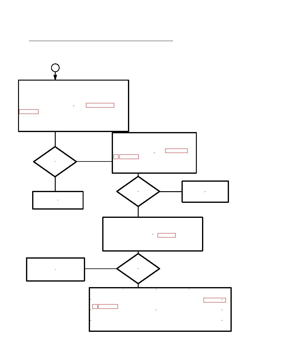
NO AIR FLOW WHEN MISSION PROFILE SWITCH IS SET FOR STATIC MODE EXTERNAL
POWER `STATIC' INDICATOR ON, NBC SWITCH OFF, EXTERNAL HYDRAULIC PUMP
INDICATOR ON Continued.
1
Shut off power to system.
Remove connector plugs from SV2 and SV9.
Remove connector 1A4A1W3P1.
Check continuity of cable per Appendix F,
P13-B, P1-a to P14-A, & P1-b to P14-B.
Gain access to cable assembly
1A4A1W1.
Test for continuity per Appendix
Does
Yes
J1-W to J3-W, J1-a to J3-a, & J1-b
No
to J3-b.
exist?
No
Does
Repair or replace
No
cable assembly
Repair cable assembly
exist?
1A4A1W1.
1A4A1W3.
Yes
Gain access to cable assembly
1A4W6.
Test for continuity per Fig 3-5 sheet
4 P1-a to P2-a, P1-b to P2-b, P1-U to
P2-U & P1-W to P2-W.
Does
Notify direct support to
No
repair cable assembly
exist?
1A4W6.
Yes
Gain access to inside of control panel.
Do a continuity check of the electrical wiring per Appendix
J2-b to A4TBGND, J2-a to A4S15-5, & J2-a to A4S1B-9.
Repair wiring as required.
2-38


