TM 10-5410-228-10
1.18 THEORY OF OPERATION.
The CBPS is supplied with communications equipment that allows the crew to maintain radio
communications during operation. The radios, supplied by the gaining unit as part of its Basis of Issue,
functions similar to any vehicle-mounted radios during mobile operations. The driver and/or passenger have
the ability to fully control the radios. They also have the ability to activate/deactivate the RRA stored inside
the LMS. The RRA allows most of the radio functions to be transferred inside CBPS during static operations
which leaves driver and passenger free to perform CBPS mission-essential tasks.
a. Mobile Mode. During mobile mode, radios are operated as any vehicle-mounted radio by driver and
passenger according to TM 11-5820-890-10-1.
b. Transition from Mobile Mode to Static Mode. When CBPS is parked and crew prepares to deploy
CBPS, driver and/or passenger switch control of radios to LMS crew. This relieves driver and/or
passenger from responsibility of monitoring radio traffic and frees them to perform other tasks.
c.
Static Mode. During static operations, LMS crew is responsible for monitoring and controlling radio
traffic. The RRA allows LMS crew to hear both long-range and short-range radio transmissions via
two loudspeakers. The LMS crew can fully control (transmit, receive, channel select, frequency hop)
long-range radio using HRCRD. The short-range radio is limited to transmit and receive functions
during static mode operations.
1.19 DESCRIPTION AND USE OF OPERATOR'S CONTROLS AND INDICATORS.
The following identifies and describes controls and indicators the operator will use to support radio
functions. Refer to Appendix A for associated manuals.
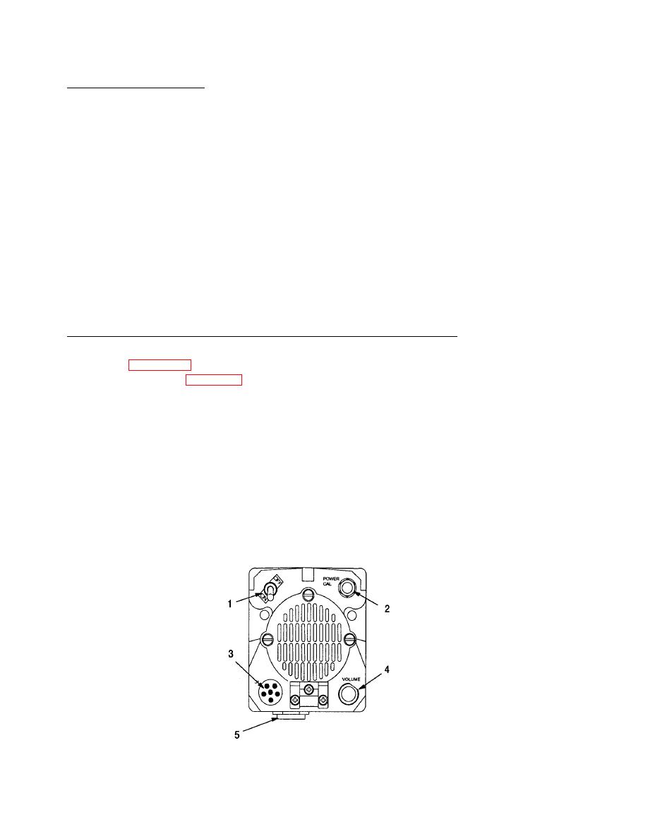
a. LS-671 Loudspeakers (figure 1-9).
(1)
Power Switch (1). Turns loudspeaker on and off. Activates power indicator lamp (2) when set to
ON position.
(2)
Handset Connector J2 (3). Connects handset or HRCRD.
(3)
POWER CAL Indicator Lamp (2). Lights when power switch (1) is set to ON position.
(4)
VOLUME Control Knob (4). Adjusts volume level of loudspeaker or handset (if connected). To
adjust volume level of handset, turn knob clockwise to increase volume or counterclockwise to
decrease volume. To adjust volume level of loudspeaker, pull and turn knob clockwise to
increase volume or counterclockwise to decrease volume.
(5)
Connector J1 (5). Connects to radio mounting base with cable marked SPEAKER supplied with
system.
Figure 1-9. LS-671 Loudspeaker Controls
1-24


