T.O. 33B-1-1
6-56
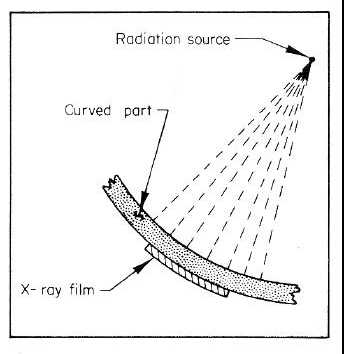
Figure 6-25. Preferred Geometry for Radiography of Curved Surfaces.
6.7.2.7
Focal spot size.
The ideal would be to have a pin point source of radiation. Though microfocus tubes approach it, in actual practice this
is impossible, and radiation sources have finite dimensions. The actual focal spot size in an X-ray tube is the projected
area being bombarded by electrons from the heated filament; in gamma radiography, it is the radioactive pellet. To
reduce the apparent size, the X-ray target is positioned at some small angle, and from the position of the X-ray film the
area appears as the projection of this focal spot on the film plane. This projection is referred to as the effective focal
spot. Focal spot sizes must increase with increasing kilovoltage rating to prevent the melting of the target material.
Radiation is being emitted from the entire area of the effective focal spot. These various radiation are projected at
different angles through the test object and spread the image of a sharp edge over a finite distance on the film.
Examples of the formation of shadow projections are shown Figure 6-23. What has been said about focal spot size in
X-ray tubes also applies to gamma radiography where the pellet of radioactive material functions as the focal spot. The
relatively large size of the pellets accounts for the inferior definition obtained with gamma radiographs.
6.7.2.8
Source To Film Distance.
The sharpest image would be formed by having a source-to-film distance (SFD) so great that the rays would be parallel
at the film plane (see Figure 6-23). However, since radiation intensity or quantity is diminished in relationship to the
inverse square of the distance, the radiation quantity available to expose the film would be very small, and exposure
times would become impractical. Therefore, in the production of the radiographic image, economics and practicability
must be considered. It is recommended that the longest practical SFD be used for critical exposures to improve image
sharpness. If the source to film distance is changed, the following formula can be used to correct the exposure.
Because an increase in distance causes a decrease in beam intensity as explained in the next paragraph, only the
intensity is changed. Do not change the kilovoltage when correcting for SFD changes.