T.O. 33B-1-1
5-23
5.2.1.3.5
Video Filtering.
Some instruments provide varying degrees of filtering of the rectified waveforms. Filtering smoothes out the
waveform, but some loss of information occurs. With minimum filtering, the presentation has greater resolution and
signal definition. Video filtering may also affect the vertical linearity of the instrument.
5.2.1.3.6
Sweep Delay.
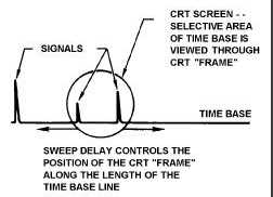
The Sweep Delay control determines what part of the time base is viewed on the display. Figure 5-22 shows a time
base with an area circled to frame the portion of the time base that an inspector wants to view on the instrument
display. Adjustments to the Sweep Delay move the frame to the desired portion of the time base, that is, Sweep Delay
delays the start of the sweep with respect to the start of the time base.
Figure 5-22. Relationship of CRT Sweep to Time Base.
5.2.1.3.7
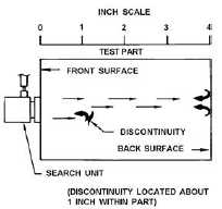
To see how the Sweep Delay works, consider the inspection shown in Figure 5-23. Under certain control settings (or
immersion testing) an instrument with a CRT might have a sweep appear as in Figure 5-24 showing only the front
surface and discontinuity signals. By adjusting the Sweep Delay to move the “frame” to the right along the time base,
the display shown in Figure 5-25 is obtained. Note that the front surface signal now appears on the far left and the
back surface signal can now be viewed also. The distance between the front surface and the discontinuity signals has
not changed from Figure 5-24.
Figure 5-23. Ultrasonic Contact Inspection.


