T.O. 33B-1-1
4-43
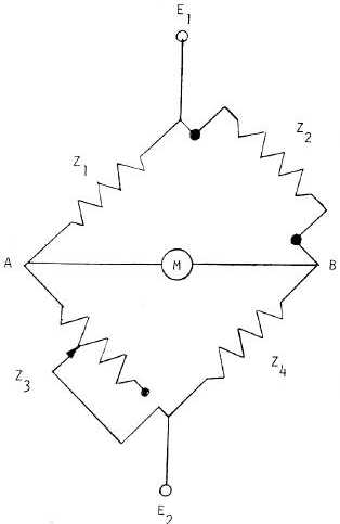
Figure 4-37. Basic Bridge Circuit.
4.4.3.16
Amplification Circuits.
The unbalance in the bridge circuit due to an impedance change at the test probe results in a change in signal
amplitude, signal phase or both. These signal changes must be amplified, detected or demodulated, and processed for
presentation on the output device (meter, scope, or recorder, etc.). The flaw signal may be only several microvolts in
amplitude and may require amplification of one thousand to one million times for further processing and display. The
frequency content of the flaw signal can range from very low (essentially DC) to the maximum operating frequency of
the eddy current instrument. This defines the distortion-free frequency response of the amplifier. The amplifier must
also be very stable with very little drift in order to maintain the required sensitivity and calibration throughout the
duration of the test.
4.4.3.17
Special Circuits And Processes.
A wide variety of electronic techniques have been developed for particular inspection problems in eddy current testing.
The circuits used depend upon the type of output, the type of flaw to be detected, or when a particular test variable
(such as lift-off) must be suppressed in order to detect other conditions. The following circuits are commonly used by
many eddy current test instruments.
4.4.3.18
Amplitude Detection.
If an eddy current system is required which only needs to detect signal amplitude changes without the use of phase
information, amplitude detection with a simple diode type detector can be used. The diode rectifies the bridge output to


