T.O. 33B-1-1
3-34
current level. A higher current will be required to form discernible magnetic particle indications. At the same time,
leakage fields from minor surface variations can attract and hold the magnetic particles, forming a background that
makes indications of true discontinuities less distinct. Increasing the magnetizing force or current will also increase the
intensity of this background. The proper magnetizing force or current is then one strong enough to produce indications
of the discontinuities that must be detected and yet is not too strong so that the background masks the indications
sought.
3.3.11.4.2
Direct Contact.
A problem arises when deciding what current is to be used for a given part, particularly when the part has a
complicated shape. A rule of thumb from ASTM E 1444 suggests currents from 300 to 800 amperes per inch of part
diameter when the part is reasonably uniform and cylindrical in shape. Except for some special alloys the use of
current values in the upper half of this range will result in excessively high field strength thus impeding the detection
of discontinuities. Generally, the diameter of the part SHALL be taken as the largest distance between any two points
on the outside circumference of the part. However, as a starting point, use the lower limit of such rules of thumb as the
initial magnetization current level. From this point, either with use of a gauss meter or shim indicators, the correct
current level can be found.
3.3.11.4.2.1
The use of the rule-of-thumb for excitation currents is fairly straightforward in the case of uniform cylindrically shaped
parts. On parts having complicated shapes, such as irregular forgings, machinery parts, weldments or castings, the use
of any rule-of-thumb is often not practical. In these cases the inspector must rely on judgment and past experience and
aids such as the shims or gauss meter previously discussed, to help in the selection of the optimum current level.
Experience with similar parts, which do have discontinuities, is especially helpful in this respect.
3.3.11.4.3
Central Conductor.
Induction current requirements using a central conductor will depend upon the part's size and the diameter of the
opening through which the conductor is to be located. In the case of a centrally-located conductor, suggested currents
from an old “rule of thumb” may range from 100 amperes per inch of hole diameter to as much as 1000 amperes per
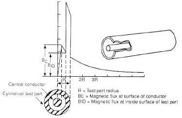
inch, depending upon part material and the nature of the suspected discontinuities. Keep in mind that the magnetizing
field strength around a central conductor decreases with distance away from the conductor. The strongest flux field is
present at the inner surface of the hole through which the central conductor passes as shown in Figure 3-25.
Not only discontinuities that are parallel with the central conductor are detectable using the central conductor
technique, but radial discontinuities at the ends of holes and openings can be detected, since some portion of the
magnetic lines of force will intercept these discontinuities.
Figure 3-25. Magnetic Flux Distribution in a Central Conduction and a Cylindrical Test Part