T.O. 33B-1-1
2-86
of the part. This is greater than the yield point, and the fracture is accompanied by some distortion. Cracks caused by
overloading are relatively large and are further magnified by distortion, making them easy to detect visually without
penetrant inspection.
2.7.6.2.3.1
Fatigue Cracks.
Fatigue cracks are caused by repeated or cyclic loads that are below the yield strength of the metal. They initiate after a
large number of load cycles usually at a surface imperfection such as a pit, scratch, tool mark, or at sharp change in
cross-section. The initial crack is very small and forms a quarter or half arc around the initiation point and then stops.
After an additional number of load cycles, the crack grows slightly. This growth-arrest cycle produces a characteristic
pattern on the fracture face, termed clam shell or beach mark pattern. Fatigue cracks have many common features.
They occur in regions of high stress; are perpendicular to the direction of principal stress at their origin; and are
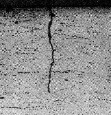
transgranular. Figure 2-33 is a good example of a fatigue crack. Transgranular means the cracking progresses through
or across the grains of metal rather than around them. Fatigue cracking occurs on a wide variety of parts and is
considered a defect. It will continue to grow in-service, and the rate of growth increases as it becomes larger.
Figure 2-33. Micrograph of a Cross-Section through a Fatigue Crack Showing the Transgranular Progression.
2.7.6.2.3.2
Stress Corrosion Cracks.
Stress corrosion cracking is caused by a combination of stress and corrosion action. The stress may be either from
service loads or a residual stress in the part. The residual stress can cause cracking of a part that has never been in
service. Stress corrosion cracks have many of the characteristics of fatigue cracks. They occur in high stress areas at
right angles to the stress and will grow in-service. Stress corrosion cracking may form a network of fine spider web-
like cracks on the part surface. Penetrant indications of stress corrosion cracks can also appear identical to indications
of fatigue cracks. Figure 2-34 shows stress corrosion crack indications in a wheel. It is not always possible to
distinguish between fatigue cracks and stress corrosion cracks from their surface appearance. Metallurgical
examination is required to identify stress corrosion from fatigue cracks, since cross-sectioning will show stress
corrosion cracks to be between the metal grains, intergranular, while fatigue cracks are transgranular breaks through
the metal grains. Figure 2-34 is a micrograph of a cross section through a stress corrosion crack. As with fatigue


