Pump Unit Assembly/
To remove control paneI assembly, electrical wires
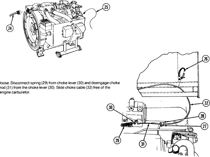
Unscrew engine disconnect cable (24) from rear of engine. Also discon-
Engine disconnect
and control cables must be disconnected from the
nect wire (25) connected between STOP-RUN-START SWITCH and the
cable (24)
engine. These wires and cables are subcomponents
oil pressure switch.
Wire (25)
of the control panel assembly.
Oil pressure switches on engines manufactured
before January 1969 are at the front end of the
engine.
Oil pressure switches on engines manufactured after
January 1969 are mounted at the rear of the engine.
Tiedown straps (26)
Cut and discard electrical tiedown straps (26) securing the choke cable to
Setscrew (27)
the frame. Loosen but don't remove setscrew (27), until clamp (28) is
Clamp (28)
Spring (29)
Choke lever (30)
Choke rod (31)
Choke cable (32)
TM 3-4230-209-30&P
2-35