TM 5-6350-264-14&P-9
NAVELEX EE 181-AA-OMI-100/E121 DZ-204
T.O. 31S9-2FSS9-1-9
CHAPTER 2
OPERATING INSTRUCTIONS
Section I. OPERATING PROCEDURES
2-1.
CONTROLS AND INDICATORS. There are no
operator
controls
or
indicators
applicable
to
this
equipment.
2-2.
NORMAL OPERATING PROCEDURES.
The AA is ready for operation after it is installed, tested,
and connected to the J-SIIDS Control Unit. Since the
startup and shutdown of the AA is dependent upon the
presence or absence of power from the J-SIIDS Control
Unit, no operating procedures are required.
2-3.
EMERGENCY OPERATION. Operation with
incomplete surveillance coverage or faulty tamper circuit
should be held to a minimum. Extended periods of
operation on battery (stand-by) power should be avoided.
2-4.
UNUSUAL
OPERATING
CONDITIONS.
Relocation or storage of large objects within close
proximity of equipment cabinet will reduce effectiveness
of audible signal.
Section II. THEORY OF OPERATION
2-5.
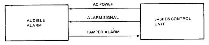
FUNCTIONAL DESCRIPTION. The Audible
Alarm provides an audible indication of an alarm
condition when it receives an alarm signal from the J-
SIIDS Control Unit. An alarm signal switches on
electronic circuitry that produces a loud (min 108 db @
10 ft), varying (500 to 2, 000 Hz) tone. This alarm
indication will continue until the cause of the alarm has
been removed and the Control Unit (CU) has been reset.
Primary ac power is provided by the CU. This ac power
is rectified to dc and
used to operate all electronic circuitry including the
battery charger. Emergency power is provided by the
battery. If ac power fails, the AA will automatically draw
operating power from the battery. A tamper alarm is
automatically initiated if the AA enclosure door is
opened, if the enclosure is pried away from its mounting
surface, or if the inner and outer enclosures are shorted
together. Figure 2-1 is a simplified block diagram.
Figure 2-1. Audible Alarm Simplified Block Diagram
2-1/(2-2 blank)