TM 5-3740-214-14
CONTROL PANEL
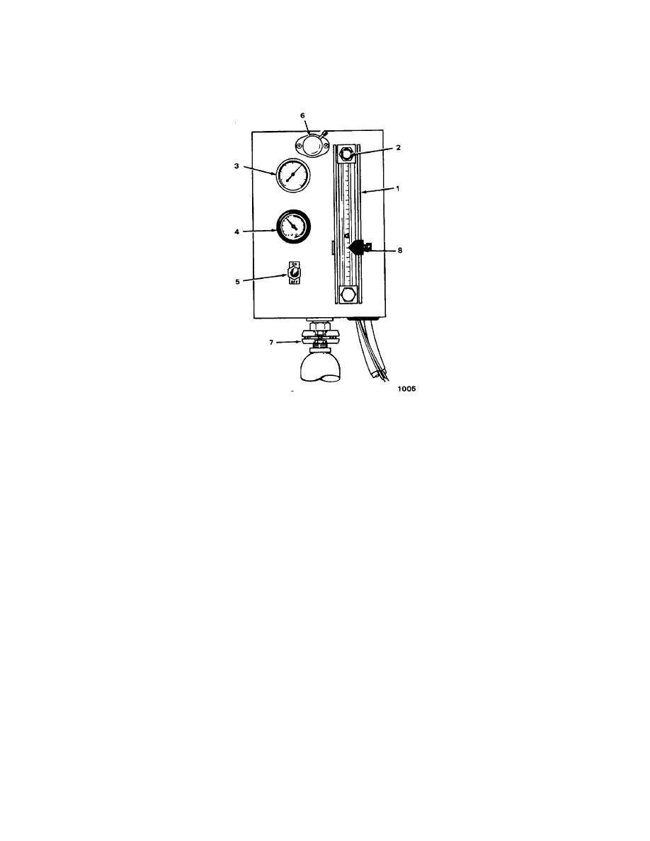
Figure 1-3. Controls and Indicators
The control panel is made up of eight major parts.
FLOW METER (1). Allows the operator to monitor the insecticide flow rate.
CONTROL NEEDLE VALVE (2). Allows the operator to regulate the insecticide flow rate.
TEMPERATURE GAGE (3). Allows the operator to monitor the insecticide temperature.
PRESSURE GAGE (4). Allows the operator to monitor the air pressure produced at the nozzle assembly.
SOLENOID VALVE SWITCH (5). Allows the operator to turn the insecticide flow on and off from the drivers position.
CONTROL PANEL LIGHT (6). Lights up the control panel for night-time operations.
UNIVERSAL JOINT (7). Allows the operator to adjust the control panel to a perpendicular position. If the flow meter is
not pointing straight up and down, the flow rate reading during operation will be incorrect.
FLOW POINTER INDICATOR (8). Indicates the correct point for the float ball to reach during operations. The pointer
shows the correct flow rate for the insecticide being sprayed.
1-4


