TM 3-6665-209-35
1
Test valve plunger
22
Rubber tubing
43
Lockwasher
2
Test valve adapter
23
Panel guide bracket
44
Nut
3
Test valve sleeve
24
PILOT light DS1
45
Nut
4
Test valve spring
25
Lockwasher
46
Lockwasher
5
Setscrew
26
Screw
47
Lockwasher
6
Test valve bushing
27
Incandescent lamp
48
Nut
7
ACCEPT light DS3
28
Lockwasher
49
Nut
8
REJE CT light DS2
29
Nut
50
Lockwasher
9
Pressure gage
30
Bracket
51
Screw
10
Screw
31
Chassis base
52
Screw
11
Copper tubing
32
Rubber grommet
53
Screw
12
Setscrew
33
Nut
54
Elbow
13
Test valve flange
34
Lockwasher
55
Adapter
14
Screw
35
Line receptacle connector J3
56
Bleeder housing
15
Test valve collar
36
Screw
57
Copper tubing
16
Rubber tubing
37
Power cord
58
Screw
17
PUSH TO CALIBRATE switch S2
38
Fuse F1
59
Valve test switch S3
18
Mode switch S4
39
Fuse holder XF1
60
Switch bracket
19
Panel handle
40
Electrical plug connector
61
Nut
20
PUMP toggle switch S5
41
Screw
62
Lockwasher
21
LINE toggle switch S6
42
Test counter receptacle connector J2
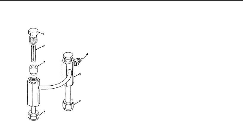
Figure 4-Continued.
c. Disassembly.
rubber tubing (3) that is inside the balance
(1) Remove both balance orifice caps (1).
orifice holder.
(2) Remove the orifice 04 (2) from the
(3) Remove the orifice 03 from the rubber
tubing that is inside the balance orifice
holder.
1
(4) Remove the /2-inch long rubber tubing (3)
from the bottom of each chamber of the
balance orifice holder.
d. Cleaning and Inspection.
(1) Clean the orifices 03 and 04 with clean dry
compressed air.
Make certain all
passages within the balance orifice holder
are clean.
(2) Inspect
both
rubber
tubings
for
deterioration and damage. The rubber
tubings are used to mount the orifices and
to provide airtight seals within the balance
orifice holder thus making all air pass
through the capillary opening.
(3) Inspect the balanced orifice caps, coupling
adapters, flared tube nuts, and balance
orifice holder for damage.
1
Balanced orifice cap
5 Balance orifice holder
e. Assembly.
2
Orifice 04
6 Flared tube nut
(1) Select the balance orifices 03 and 04 (2)
3
Rubber tubing
7 Flared tube nut
according to table I of TM 3-6665-209-12.
4
Coupling adapter
The milliliters per minute number and the
word FLOW with an arrow are etched on
Figure 5. Balance orifice holder.
each orifice.
AGO 8069A
11

