TM 10-5410-228-24
1.15 ELECTRICAL SYSTEM Continued.
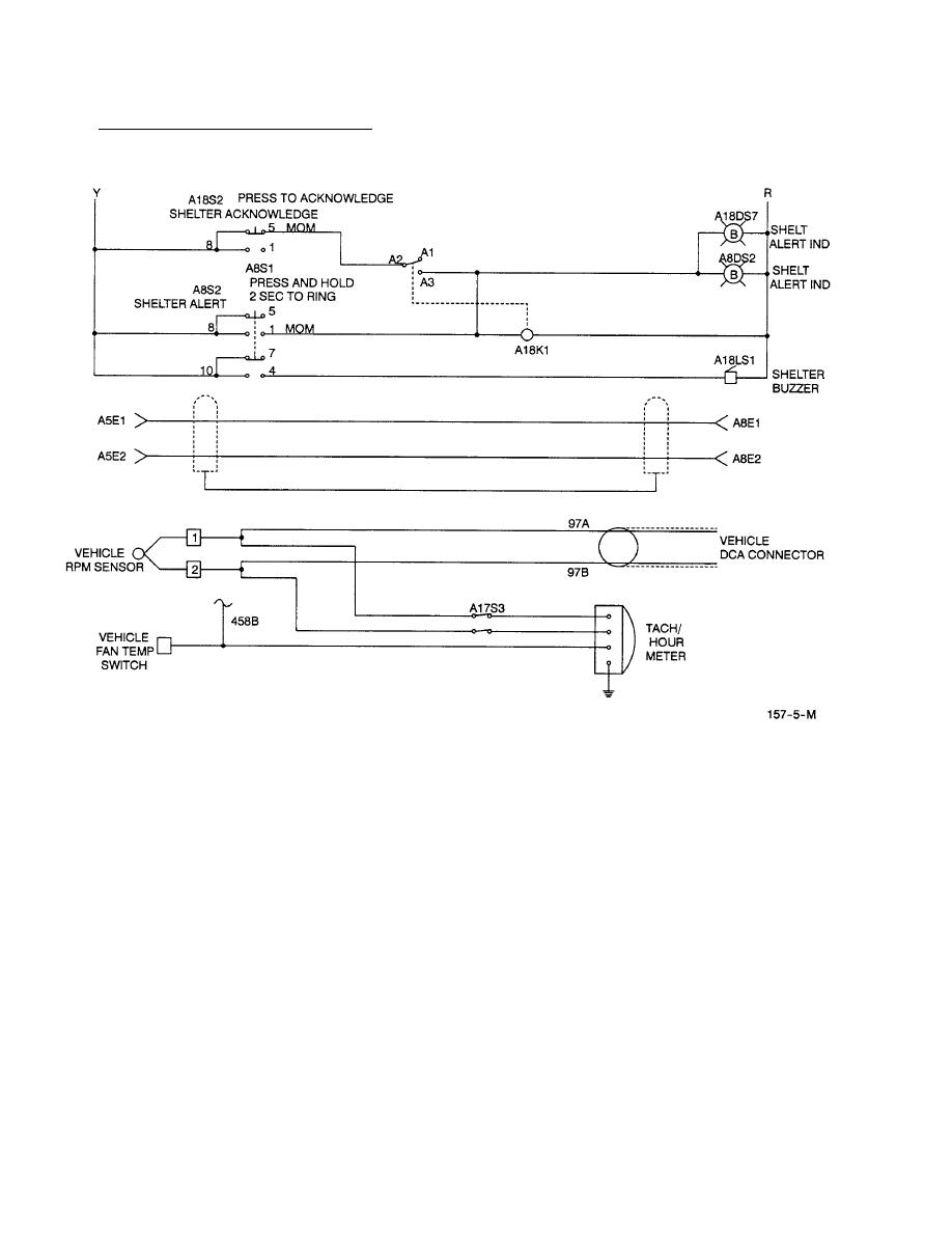
Figure 1-8. System Schematic (Sheet 5 of 5)
NOTE
The POWER MODE selector must be set to internal (INT) mode to operate CBPS using ECV
power.
a. +24VDC. When the EVC OFF/RUN/START switch is set to RUN and CBPS is operating on
A17K1. The +24VDC switched by A17K1 is applied to the 24VDC bus on Rear Control Panel.
b. 115 VAC, Single Phase. One of the outputs from 24 VDC bus is routed to inverter (1A4A13) through
1A4A4 J11 and cable 1A4W11 to inverter at 1A4A13 J1. The inverter converts +24 VDC to a 115
VAC output on connector 1A4A13 J2 which is routed back to the Rear Control Panel through cable
1A4W12 and 1A4A4 J6 and applied to pins 17 and 19 on the POWER MODE selector A4S1-B.
115 VAC, single phase is used for only one application in CBPS system. It provides power to 1A4A10
Receptacle Panel located on rear of the LMS. The receptacle panel provides a source of power to
operate portable recirculation fans positioned on floor of Air Beam Shelter (ABS), the light sets for
lighting the ABS, and miscellaneous electrical equipment as required. All applications of 115 VAC,
single phase are used only when the CBPS is used in the static mode (the ABS must be inflated to
access the receptacle panel.
1-30


